2024.5 – Present: Suspension team lead
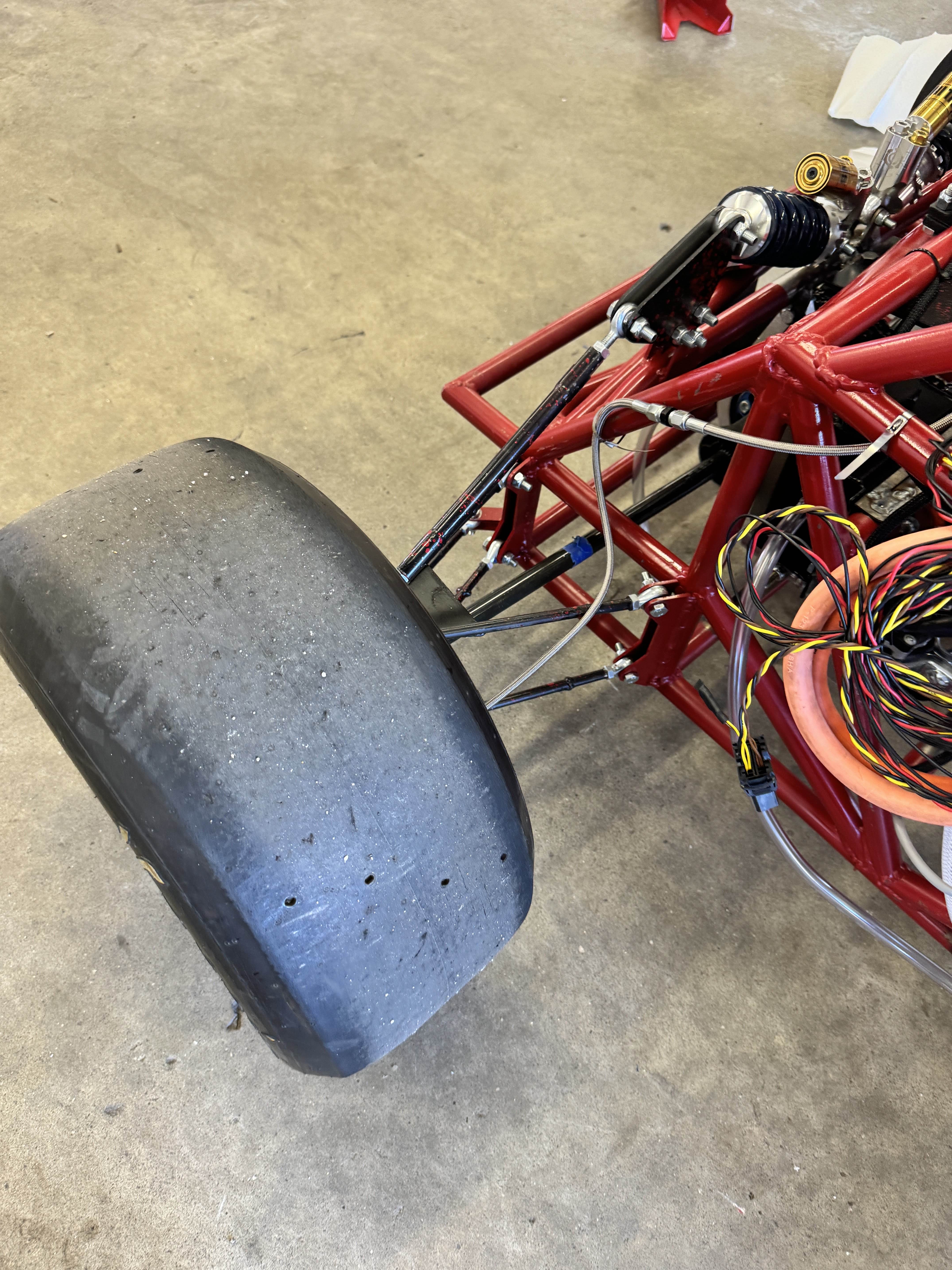
- Owned the full suspension system, including upright, A-arms (wishbones), pushrod, shock absorber, and spring assemblies.
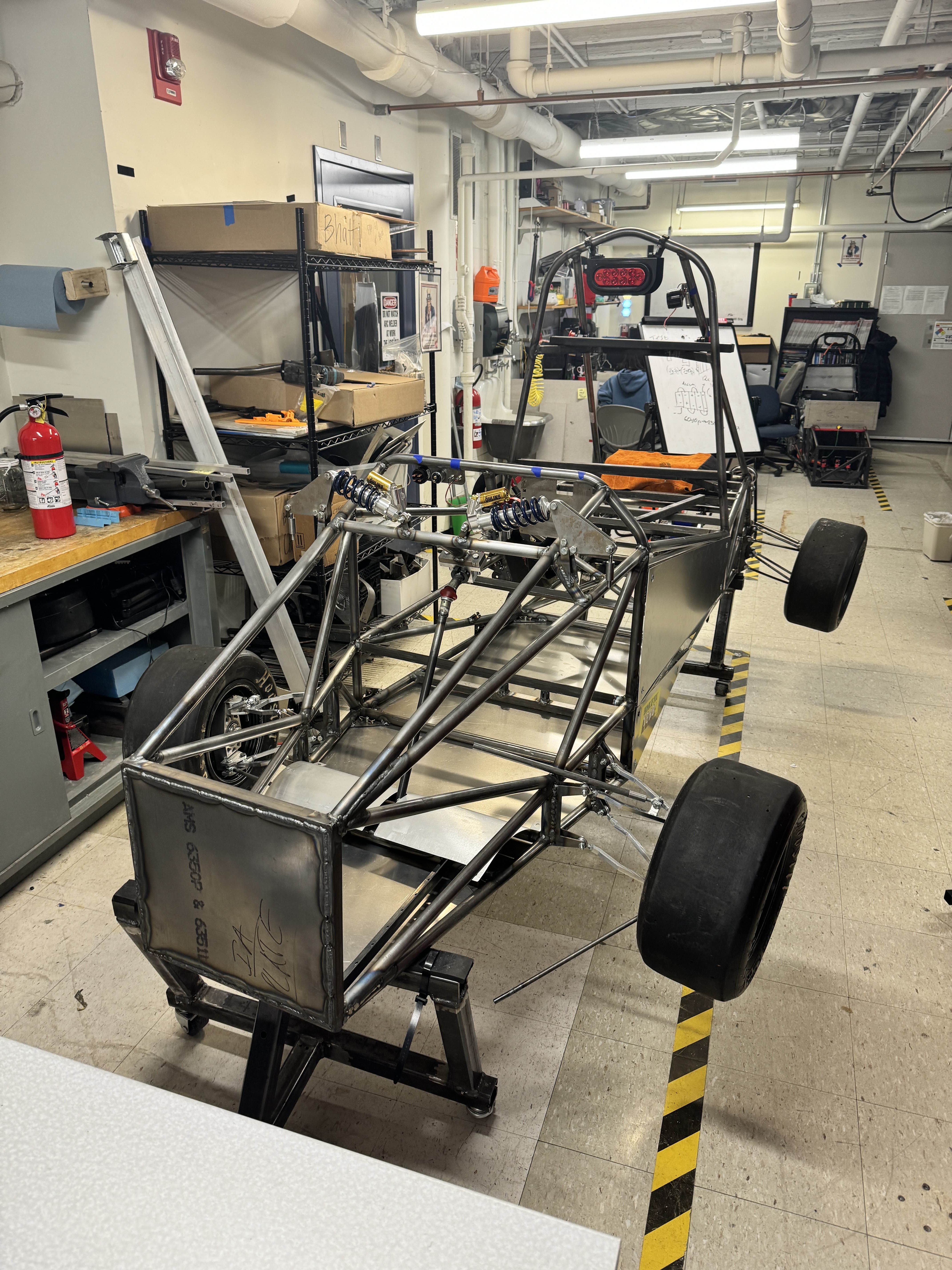
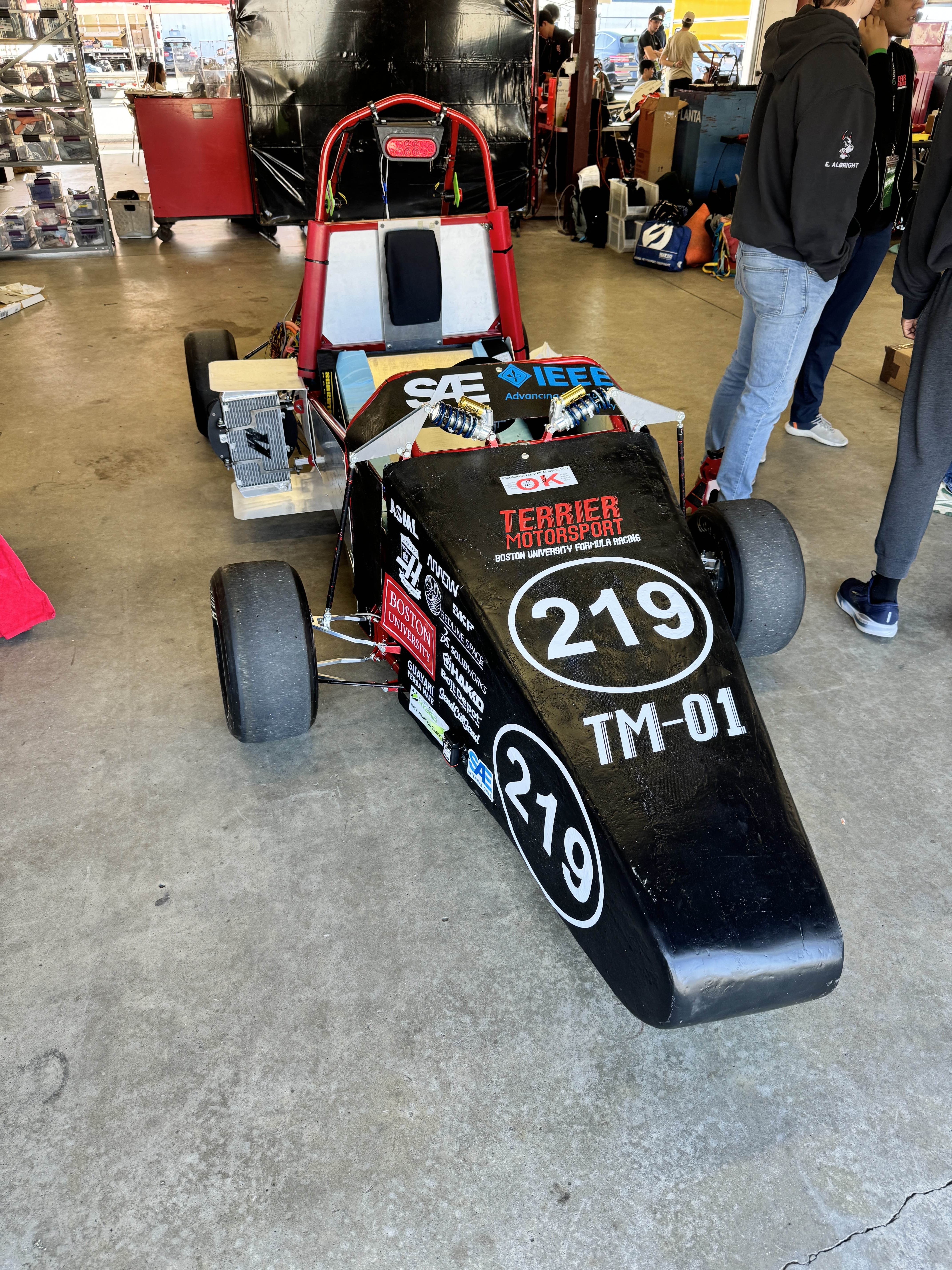
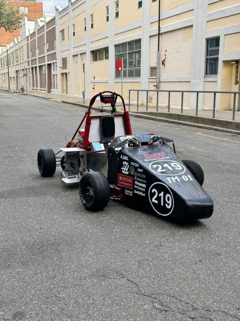
- Researched, designed, and manufactured the suspension for the TM01 (2024-25) vehicle.
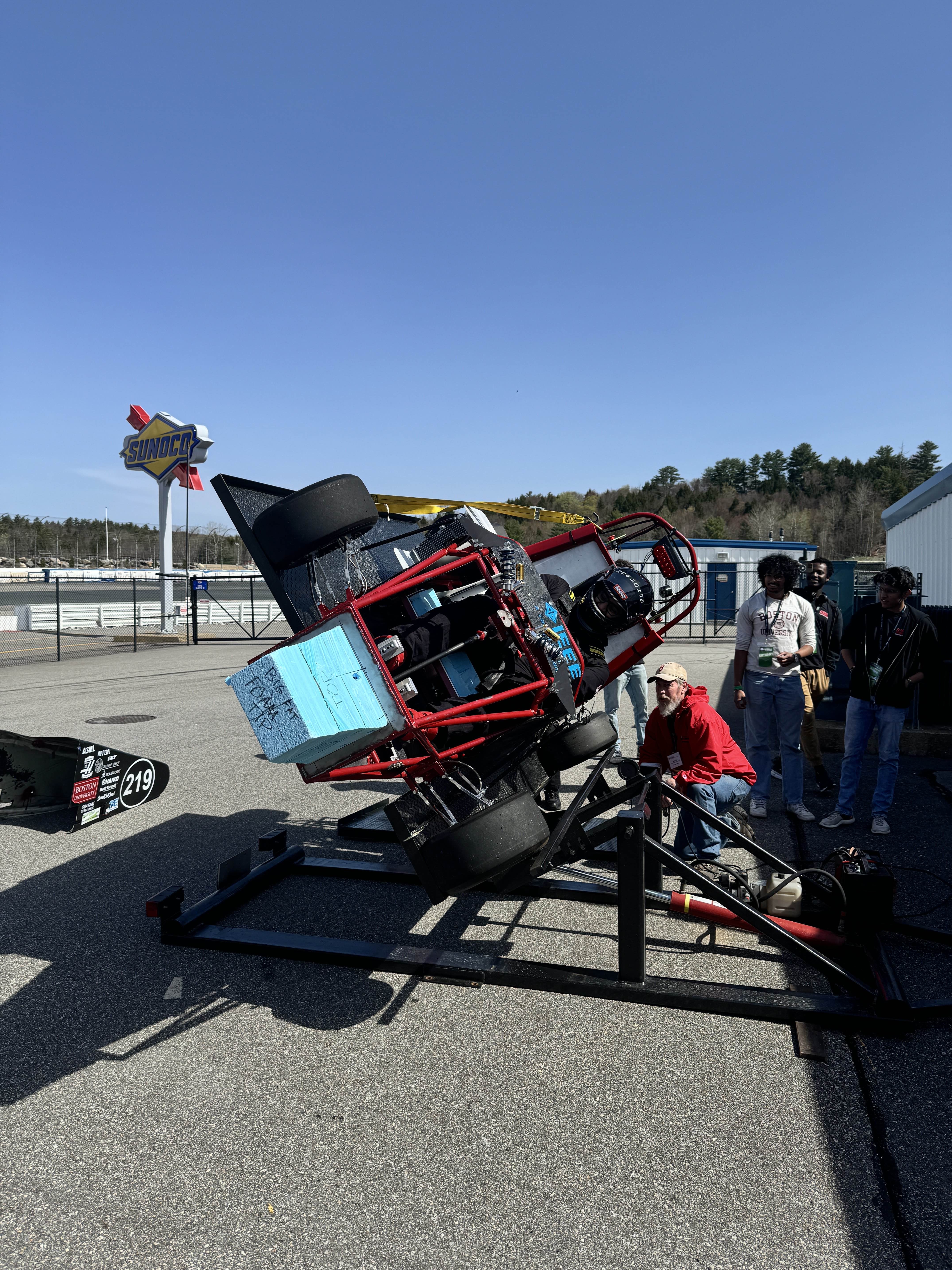
- Successfully validated suspension performance at the 2025 Formula Hybrid + Electric competition at New Hampshire Motor Speedway.
- Currently optimizing the suspension for the 2026 competition while developing an improved system for the TM02 vehicle
2023.9 – 2024.5: Powertrain team general member
- Completed intro-project of modeling a motor mount.
- Designed / manufactured cooling fan mount and shroud.
Suspension Team: Facts
2025-26 Season
- Developed upgraded TM01 suspension components over the summer and am currently manufacturing and integrating the improvements.
- Built a new suspension team of six students by hosting weekly training sessions and sharing fundamental design and engineering knowledge.
2024-25 Season
- Began suspension development with no prior documentation, self-learning fundamentals and building the capability to design and manufacture a full system.
- Served as the only returning suspension member, leading research, design, and technical decisions.
- Designed TM01 suspension with simplicity and reliability as the team’s first suspension.
- Created documentation to record lessons learned and establish a foundation for future teams.
TM01 Suspension Technical Information
Please click to see more information.
Vehicle Specification:
- Weight: 400 kg (approximate, including driver)
- Maximum speed: 60 mph
- Power source: Electricity (Li-po battery)
Geometry
Defining geometry is the first step to develop a suspension. This was carefully done towards aim of camber gain and simplicity.
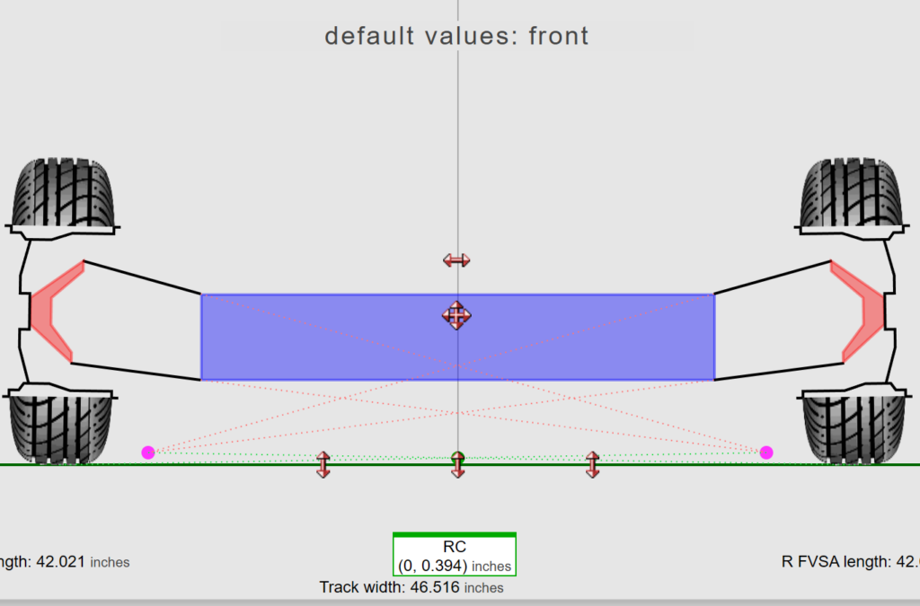
Design Goal:
- Front
- Net camber of -1 inches
- Camber of 2.2 inches at bump of 1 inches
- Rear
- Net camber of -1 inches
- Camber of -3 to -3.5 inches at bump of 1 inches
- Whole system
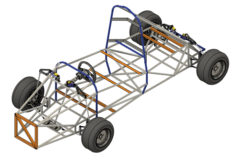
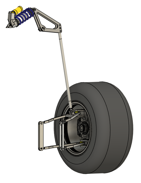
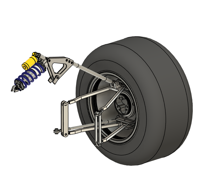
- Double wishbone suspension
- Spring, rocker, and push rod should be on the same plane for simplicity.
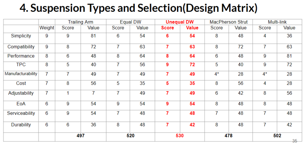
Decision matrix for suspension type analysis
CAD
Building a robust CAD model is essential for validating suspension behavior and identifying geometric errors. My model emphasized modularity and adjustability through a set of key design features.
Software Used:
- [’24–25] SolidWorks 2024
- [’25-26] Fusion 360
Key Features (Click to see details)
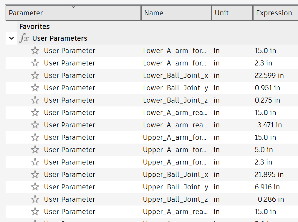
Defined and managed all hard-points in 3D coordinates to enable deterministic adjustability.
Prior to CAD modeling, all critical hard points (mounting locations, spherical bearings, rocker pivots, spring positions, etc.) are defined in a coordinate system. These coordinates are then referenced in the CAD model so each point remains independent, ensuring geometry changes are deterministic and do not propagate unintended dependencies.
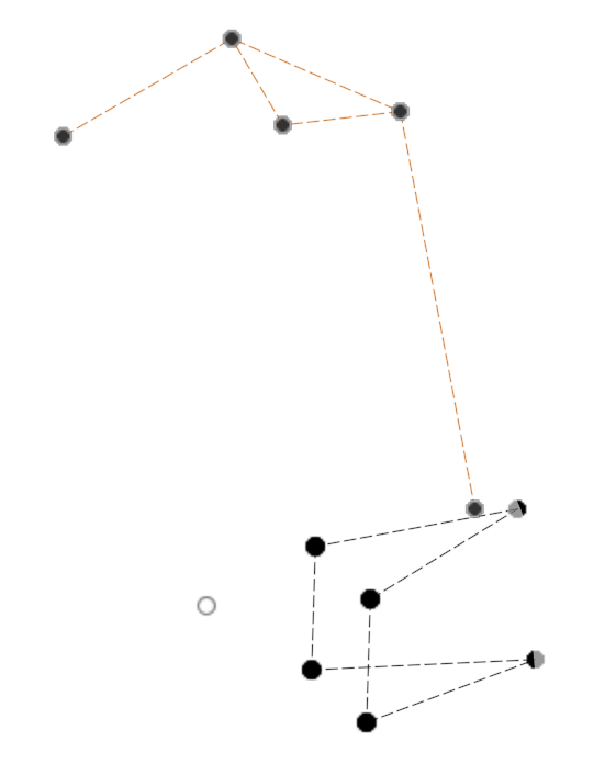
(Left): Hard-point sketch on Fusion.
(Right): Example parameters
Geometry-driven components built from reference sketches and hard-points.
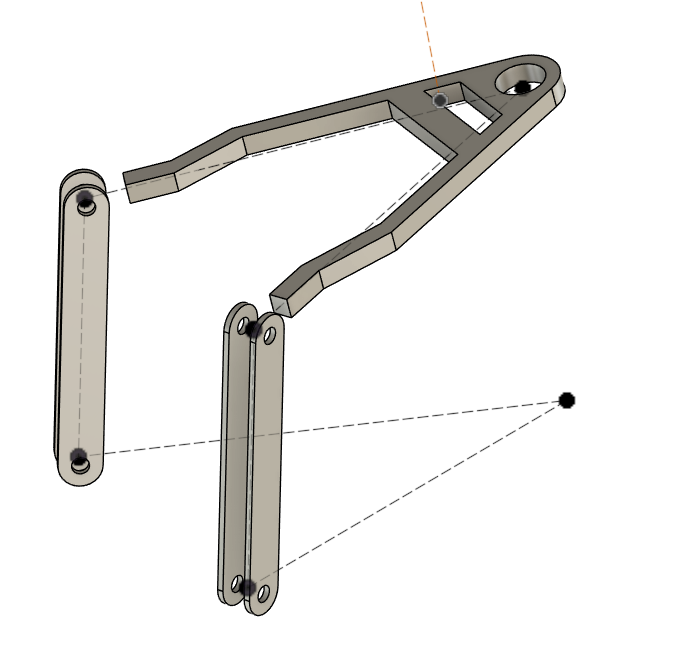
All components are referenced to master sketches and hard-points, so suspension geometry updates automatically reshape the parts. The rear assembly was created from the front by changing parameters only. No manual redesign was needed.
(Left) Upper A-arm is defined with respect to mounting position and spherical bearing positions.
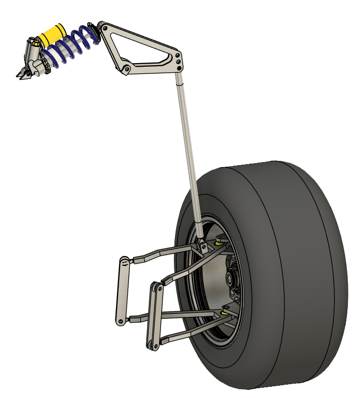
Realistic Joint Modeling for Accurate Suspension Kinematics
Each suspension joint was modeled to match its real-world mechanical behavior, using spherical, revolute, and sliding constraints where appropriate. This realistic joint setup allows the CAD assembly to move like an actual suspension system, allowing designers to find geometric errors and conflicts.
Screenshots
Shock & Springs
Choosing right parameters for shock and springs is critical in stabilizing the vehicle performance. This was done through series of calculations.
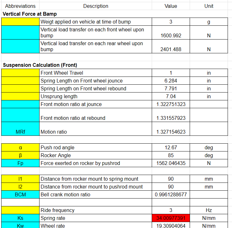
Conditions of calculation:
- Bump Scenario: 3g bump load applied
- Vehicle weight distribution:
- Front: ~80kg per wheel
- Rear: ~120kg per wheel
- Cornering case:
- Turn radius: 6m
- Speed: 60km/h
- Ride Frequency: 3 Hz
Simulation result:
- Spring rate:
- Front: 50.01 N/mm
- Rear: 86.20 N/mm
Key Theories:
Coil spring rate
Coil spring rate is how stiff a spring is and represents the force required to compress it by a unit distance. It follows this equation, which shows that it depends on material shear modulus and spring geometry.
Higher spring rate helps support loads and control body motion while it undermines mechanical grip on uneven surfaces.
Ride frequency
Ride frequency is how quickly the suspension oscillates in response to bumps and is calculated by the following equation, which is derived from natural frequency of a simple mass-spring system.
Higher ride frequency improves responsiveness and handling, and typical race cars use values in the 2.5-4 Hz range. However, increasing this frequency makes the ride stiffer and can reduce mechanical grip on uneven surfaces.
Calculations are based on research paper “Design and Optimization of Formula SAE Suspension system” by Ashish Vadhe. (Link )
FEA
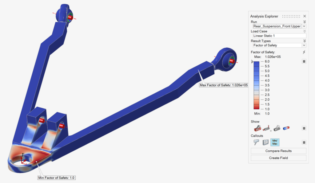
FEA was conducted to validate design and ensure FoS falls into an acceptable range.
Software used:
- Altair Inspire (for multibody FEA)
- Fusion 360 (for simple FEA)
- SolidWorks
Example FEA report:
Manufacturing
Once the design was finalized and validated, we proceeded to manufacture the suspension. Since this was our very first suspension, I was responsible for manufacturing. As this was our first suspension system, I took full responsibility for leading the manufacturing process. The following section outlines key suspension components and the methods used to fabricate them.
List of Manufacturing Method used
Machining:
- CNC milling
- Manual milling
- Drilling & Tapping
- Manual Lathe
Cutting:
- Water jet cutting
- Laser cuting
- Band saw cutting
- Wire EDM
Others
- Bearing staking
- MIG welding
- FDM
- Belt sanding
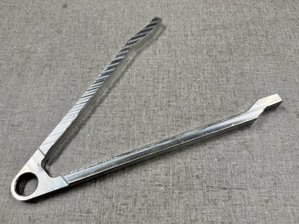
A-Arm
CNC mill: used to subtract the shape from Al 6016 block.
Video
Wire EDM: used to achieve high tolerance of +/- 0.0002 inches around boles for spherical bearing.
Video
Manual mill: used to create a chamfer of 0.02″ width with tolerance of 0.002 inches.
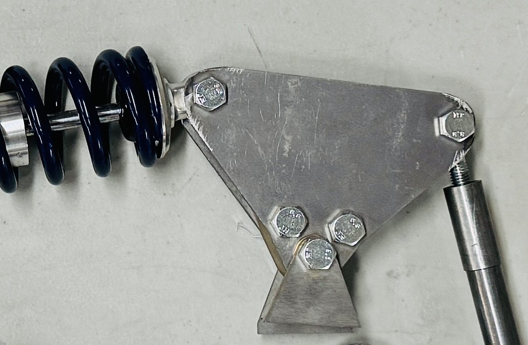
Rocker
Water jet: Used to cut sheet of Steel AISI 4130.
Video
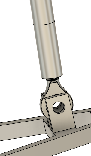
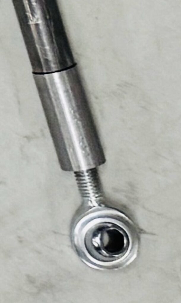
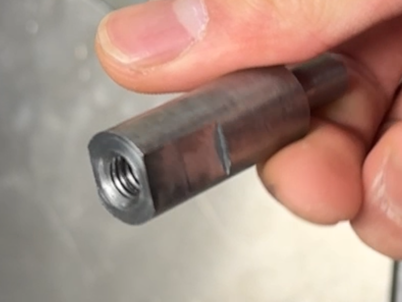
Push rod + Connector
Lathe: Used to cut Steel AISI 4130 rod / tube.
Drill: Used to tap holes for threaded rod end.
Manual mill: Used to machine flat surfaces on the connector so a wrench can grip it.