This assignment focuses on designing a motion speed control system that can deliver an aluminum rod with a rectangular cross-section onto a wooden surface without tipping over.
To achieve the shortest delivery time, the theoretical maximum acceleration was first calculated. The system was then modeled in SolidWorks using a linear motor as the actuator. Finally, a wheel mechanism was implemented to realize the desired motion while maintaining stability.
1. Theoretical maximum acceleration (a_max)
The following Free Body Diagram was constructed. In this model, the aluminum rod is accelerating to the right direction.
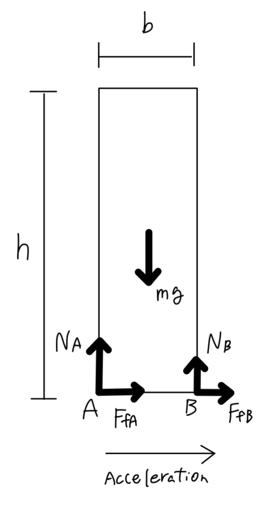
Following three equations were made.
It should be noted that when the aluminum rod is tipping, normal force and frictional force at point B becomes zero so equations can be simplified into:
By combining these equations, we obtain the following equation for theoretical maximum acceleration when the aluminum rod is tipping.
Since height is 1 foot and base side is 1 inch long, theoretical maximum calculation was calculated as;
In this project, the car must complete a 10-ft round trip. The car must have a positive constant acceleration equal to the calculated theoretical maximum acceleration until the 5-ft point, and then have a negative acceleration of the same magnitude for the return.
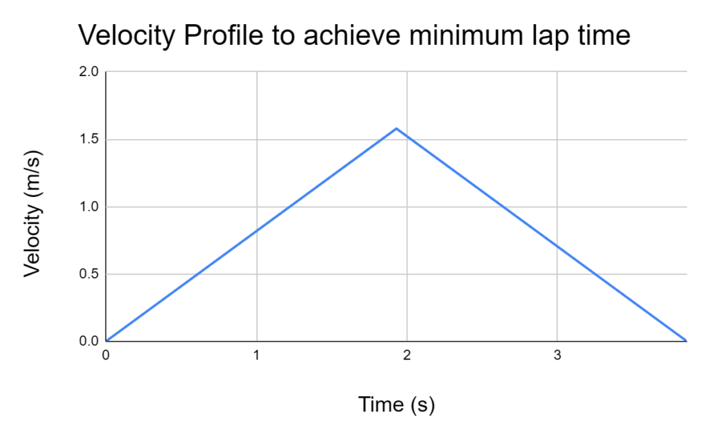
Theoretical maximum speed and time (one way) can be calculated as follows.
.Based on this result, the following velocity diagram was created.
2. Model system in SolidWorks
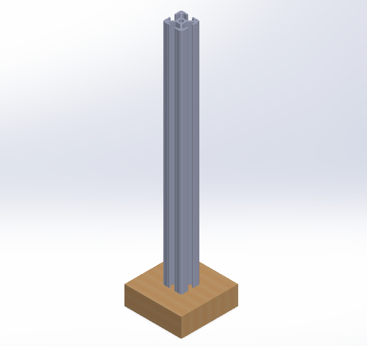
In SolidWorks, the base plate and the aluminum profile were modeled and mated as follows.
- Two points on the bottom of the aluminum profile were made coincident with two fixed points on the base plate.
- one point on the base of the aluminum profile, representing the tipping edge, was constrained coincident with the base plate.
- The base plate itself has one degree of freedom.
As a result, the overall system possesses a single degree of freedom: translation along the x-direction. A picture of the CAD model is shown below.
3. Try on Linear Motor
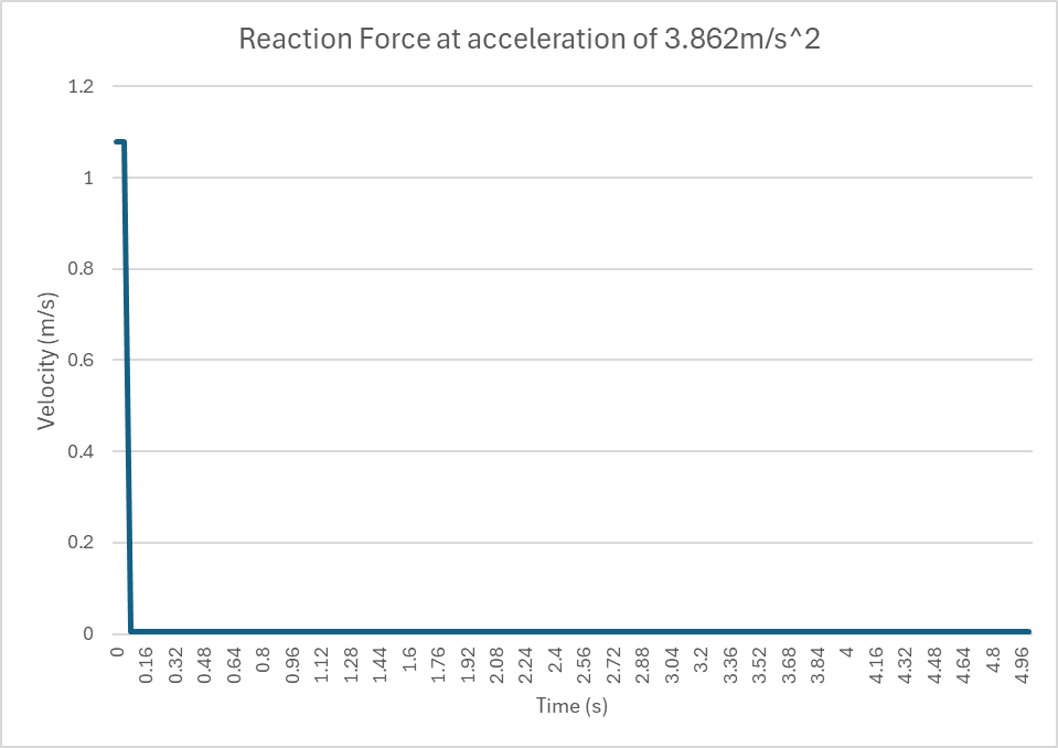
In Motion Study, A linear motor of varying acceleration was applied to the base in x-direction. The acceleration was modeled as:
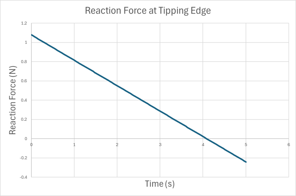
The plot of reaction force between the tipping edge of the aluminum profile and base was made. The theoretical maximum calculation could be verified by finding the time at which the reaction force becomes zero.
The obtained data is shown below and reaction force was zero at 4.0861 seconds (Interpolated between two data points).
Now the acceleration reached when the aluminum profile is tipped is calculated.
Since this almost matches with the theoretical maximum acceleration, the maximum acceleration was verified.
4. Put complete system in SolidWorks
In order to apply rotary motor and simulate the tipping, a wheel of diameter of 30mm was created and applied to the base through Pinion and Rack Mate.
In order to find the target angular velocity, following calculation was done.
It should be noted that rotary motor should achieve this angular velocity at 1.931 seconds point where the car reaches 5-ft and have maximum velocity. Now the rotary motion was applied in Motion Study.
The resultant reaction force plot is shown below.
According to the data, once the reaction force plunges after t=0, it stayed at 0.004N. It means the profile is on the verge of tipping, which verifies the maximum acceleration.
Summary
In this deliverable, the theoretical maximum acceleration of the car without tipping over the aluminum profile was calculated, and was verified in SolidWorks Motion Study. First linear motor was applied to the base, and rotary motor was applied to the mock up wheels according to the calculation of target angular velocity.
- Vertical: w/2 at two bottom edge of the ba