Based on the multibody dynamic model simulated in the previous assignment, a prototype car was build. This assignment was done in collaboration with one of classmates, Elliot Albright.
1. Design Process
Firstly, the acceleration of the car was determined. My teammate and I obtained the same result for the theoretical maximum calculation of
(1) Radius of wheels
The radius of the wheels determines the torque required for the motor and the maximum speed, as the torque and maximum speed of the motor is limited.
Condition:
- Overall weight of model: 0.6kg (calculated in SolidWorks)
- Maximum acceleration: 0.8175 m/s^2
- Motor rated torque: 0.5kg-cm (4.903 N-cm)
- Maximum motor speed: 240RPM
The required radius of the wheel is calculated as follow.
However, it should be noted that even if we have a radius of 9.99cm, the car can only get to 1.578m/s which is at 240 RPM, which translates to the radius of 6.3cm. Therefore, there is no point in making the wheels bigger than 6.3cm.
Since errors in manufacturing are expected, three types of wheels were prepared: radius of 2 inches (50.8mm), 2.5 inches (63.5mm), and 3 inches (76.2mm).
(2) Overall dimensions
The important dimensions of components were measured and a rough sketch of overall dimensions was drawn. The rough sketch is shown below.
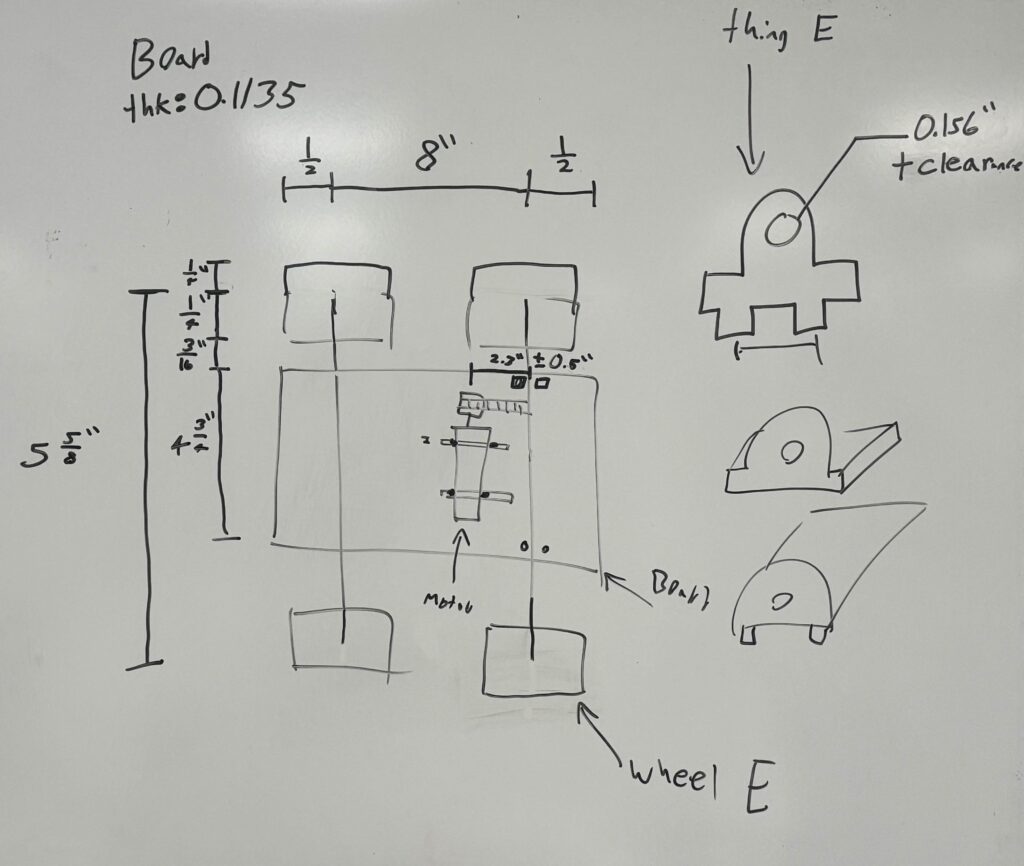
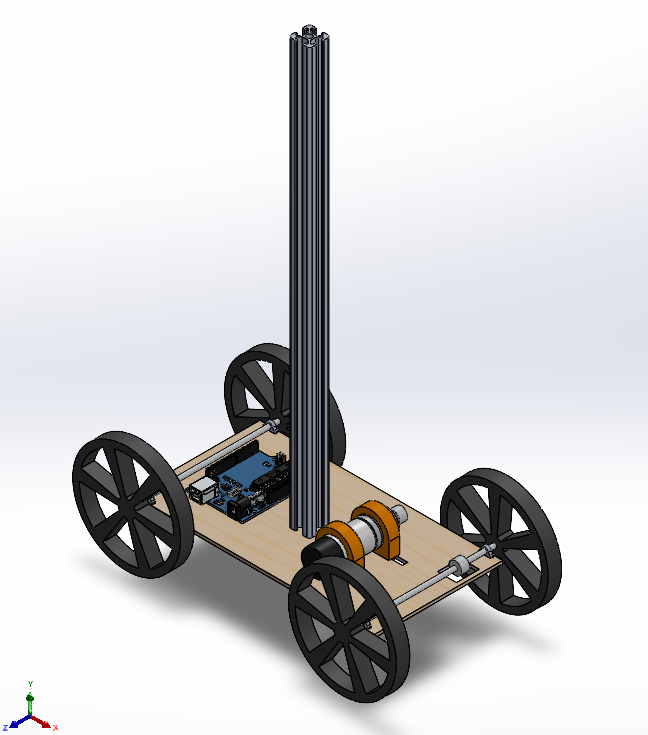
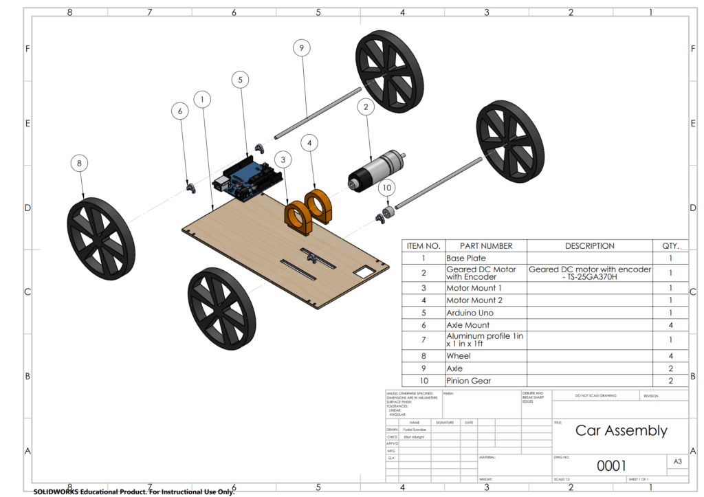
Based on this sketch, the car CAD model was created. The design and drawing are shown below. (Belt is not included.)
It should be noted that the motor mount was designed so that it can slide along the longitudinal axis, so tension on the belt between gears on motor and axle can be adjusted. Once the position is determined, it is supposed to be hot glued.
2. Construction
Based on the CAD model, the car was constructed in various manufacturing methods. The manufacturing methods are shown as follows.
| Part Name | Manufacturing Method |
| Base Plate | Laser-cutting (Balsa) |
| Axle Mounts (x4) | Laser-cutting (MDF) |
| Motor Mounts (x2) | 3D Printing (PLA) |
| Wheels | 3D Printing (PLA) -> Laser-cutting (Balsa) |
Initially wheels were 3D-printed. However, testing showed that slip never occurs, thus wheels were laser-cut to reduce weight.
3. Tests & Iteration
With the constructed prototype, the Arduino code was written, and we tested until desired motion was achieved.
(1) Construction errors
As expected, there were some errors in construction which added uncertainty for the stability of the profile. The most apparent one was the warping of the base plate, which made the top surface not flat. This slightly tilted the aluminum profile when placed, making it easier to be tipped over. Additionally, the wheels were slightly angled from vertical axis of the car, making the ride more unstable. However, significance of these errors was small as the prototype demonstrated successful carriage, while acceleration must be scaled down to account for these errors.
(2) Wheel selection
Wheels of varying radii were tested for this prototype, and we concluded that 2 inch radius wheel was enough to produce maximum velocity in 10-ft travel. This would be because we underestimated the overall weight of the car.
(2) Code
Full Arduino Code
// Illustrates closed loop control to achieve a trapezoidal velocity profile
// that accelerates linearly from 0 r.p.m., peaks at 100 r.p.m at 5 s,
// maintains that speed for 5 seconds more, and linearly decelerates to 0 r.p.m.
// in the next 5 seconds

volatile long int counter=0;
unsigned long int t0=0;
double RPM=0, error=0, lasterror=0, Kp=0.6, kd=1, target=0, v_out, t=0;
String cad="";
int v_threshold=22; // The voltage needed to overcome friction, i.e. the minimum voltage required to move the motor

void setup() {
  pinMode(2,INPUT);
  pinMode(3,INPUT);

  attachInterrupt(digitalPinToInterrupt(2),myFunction,RISING);

  pinMode(5,OUTPUT);
  pinMode(6,OUTPUT);

  Serial.begin(9600);

  t0=millis();  // This corresponds to t=0 for the control loop
}

const double a = 1.21; //ft/s^2
const double i = 1.1786; //idealizing factor
const double Df = 10; //ft
const double Db = 10; //ft
const double Tf = sqrt(Df/(a/(i*i)));
const double Tb = sqrt(Db/(a/(i*i))); //0.918
const double T = 240.0*2*PI/60.0*1/6.0/a;

void loop() {
  t=(double(millis())-t0)*1E-3;

  // Define target as a function of time
  if (t<Tf)
    target=240/T*t;
  else if (t<Tf)
    target=240/T*Tf;
  else if (t<Tf*2)
    target=240/T*Tf-240/T*(t-Tf);
  else if (t<Tf*2+Tb)
    target = -240/T*(t-Tf*2);
  else if (t<Tf*2+Tb)
    target = -240/T*(Tb);
  else if (t<Tf*2+Tb*2)
    target = -240/T*(Tb) + 240/T*(t-Tf*2-Tb);
  else{
    delay(10);
    target = 0;
  }

  getRPM(50);
  lasterror=error;
  error=target-RPM;
  v_out+=int(Kp*error) + int(kd*(error-lasterror));
  if (v_out>255-v_threshold)
    v_out=255-v_threshold;
  else if (v_out<-255+v_threshold)
    v_out = -255+v_threshold;

  cad=String(target)+","+String(RPM);
  Serial.println(cad);
  if(v_out > 0){
    analogWrite(5,v_threshold+int(v_out));
    analogWrite(6, 0);
  }
  else{
    analogWrite(6, v_threshold-int(v_out));
    analogWrite(5, 0);
  }
}

void myFunction(){
  if (digitalRead(3))
    counter--;
  else
    counter++;
}

void getRPM(int millisecs){
  long int th0, th1;
  double dt, dth;

  th0=int(counter);
  delay(millisecs);
  th1=counter;
  dt=double(millisecs)/60000.0; // [min]
  dth=double(th1-th0)/240.0;  // [rev]

  RPM=dth/dt;
}
Arduino Code was written and tested for varying target speed until we demonstrated >90% of successful demonstration.
5. Competition Video
The video of the car completing round trip of 5ft is shown.
6. Summary
In this project, the multibody dynamic model was made into real life prototype and demonstrated the successful carriage of the aluminum profile without tipping over.