Introduction
The aim of this assignment is to learn how to run motion study in SolidWorks and analyze the mechanism in terms of various mechanical parameters, such as motor torque, reaction force, etc.
Video of Motion
Link to SolidWorks File
Click here to download.
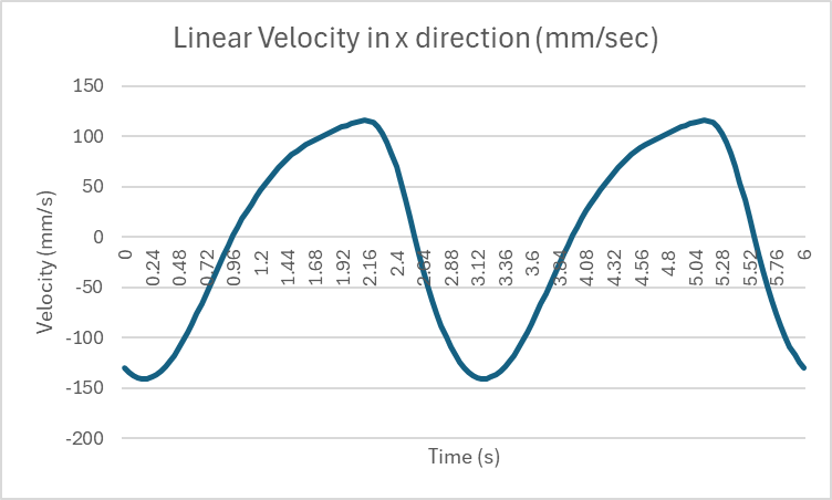
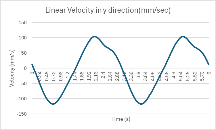
(1) Velocity in the x & y directions for the midpoint of the Extension
In Motion study, two plots showing relationship between velocities in x and y direction vs time are made and are shown below.
(a). Maximum value of the motor torque
In Motion study, a plot showing relationship between the magnitude of motor torque and time was made and is shown below.
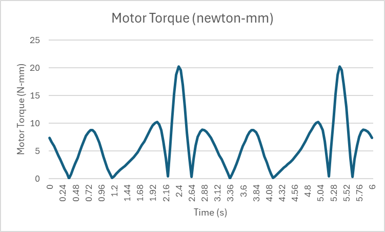
From the data, the maximum value was found and was 20.28N-mm at 2.4 and 5.4 second points. This makes sense since the the motor makes one revolution in 3 seconds (60s/20RPM) and the maximum torque is observed once in every 3 seconds.
(b) Angle of the crank for which the motor torque is maximum
The plot of motor torque vs angular displacement of crank was made and is shown below.
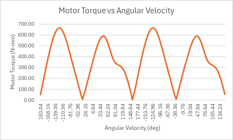
The data showed that the maximum torque occurred at -115.36 degree. This state of the mechanism is depicted below.

(c) Maximum Vertical Force exerted on Bearing / NewBearing
To find the vertical force, reaction force was measured and plotted at the hinge joint at each bearing.
The plot for Bearing (Left) is shown below.
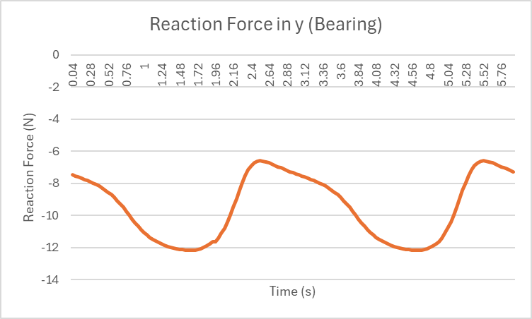
The maximum vertical force exerted was -6.60N (maximum magnitude was 12.17N). This was negative, meaning the force was downward, which makes sense due to the presence of gravity in -y direction.
The plot for NewBearing (right) is shown below.
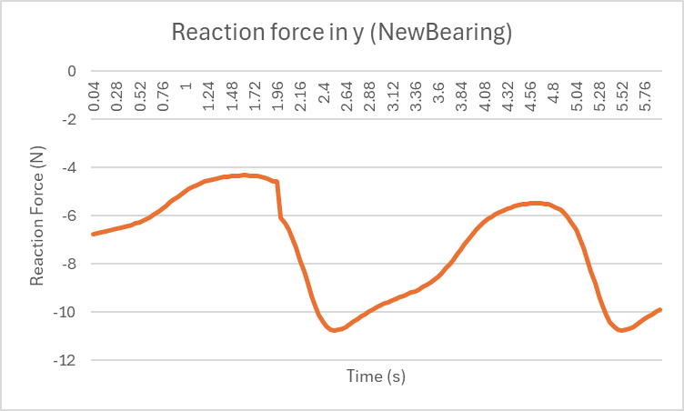
The maximum vertical force exerted was -4.32N (maximum magnitude was 10.76N).
(d) Minimum motor power required to have to move the crank at 600rpm
In order to calculate the minimum motor power required, firstly the maximum torque was made. Following equation was used to find minimum required power.
Angular velocity was calculated as follows.
Then the maximum torque was found from the motor torque vs time plot shown below.
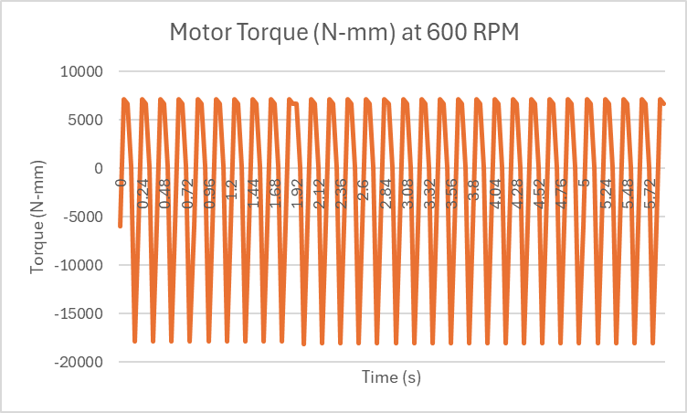
The data showed that the maximum magnitude of torque was 7.150N-m. It should be noted that the value is negative, since the motor is applying torque in the opposite direction of its motion.
By multiplying with angular velocity, it shows that the maximum power required is 449W.
This was further verified by plotting the power consumption.
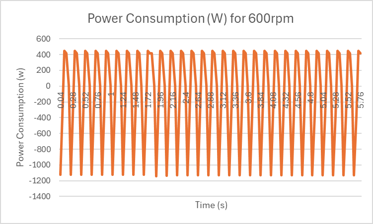
The maximum magnitude of power was found to be 449 W, which agrees with the calculated value.
(e) Meaning of negative motor torque and its relation to the motion of the mechanism link
Negative motor torque means that the motor is applying power in the opposite direction to its motion, absorbing the energy.
This happens in my mechanism link because in some portion of the motion, the mechanism’s inertia and gravity act in the direction of the motion, which requires motor to apply torque opposing that motion to maintain constant speed.
As a result, the motor experiences negative torque and negative power, meaning it is being back-driven. This represents motor’s braking phase rather than power consumption.