Introduction
The goal of this activity is to demonstrate our understanding of motion analysis and motion control. This motivated us to develop a motion system of a 2.5 degree-of-freedom using the provided aluminum extrusions, three stepping motors, and one servo motor. Our group designed a CNC Pack Board Game Player, a system capable of detecting a pack, positioning it at a shooting location, and launching it towards the opponent’s side using a rubber-band mechanism. This portfolio entry is intended to provide details of development process.
Pack Board Game
Pack Board Game is a two-player board game where players take turns shooting pucks to the opponent’s side by pulling and releasing a rubber band. The goal is to shoot all of one’s pucks to the opponent’s side; the first player to do so wins. Example images of this game is shown below.
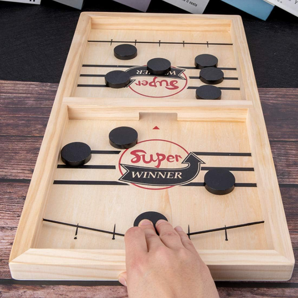
(Image from Amazon.com)
Development Process
Our group designed and developed the CNC Pack Board Game Player following the iterations below.
- Determine the overall dimensions
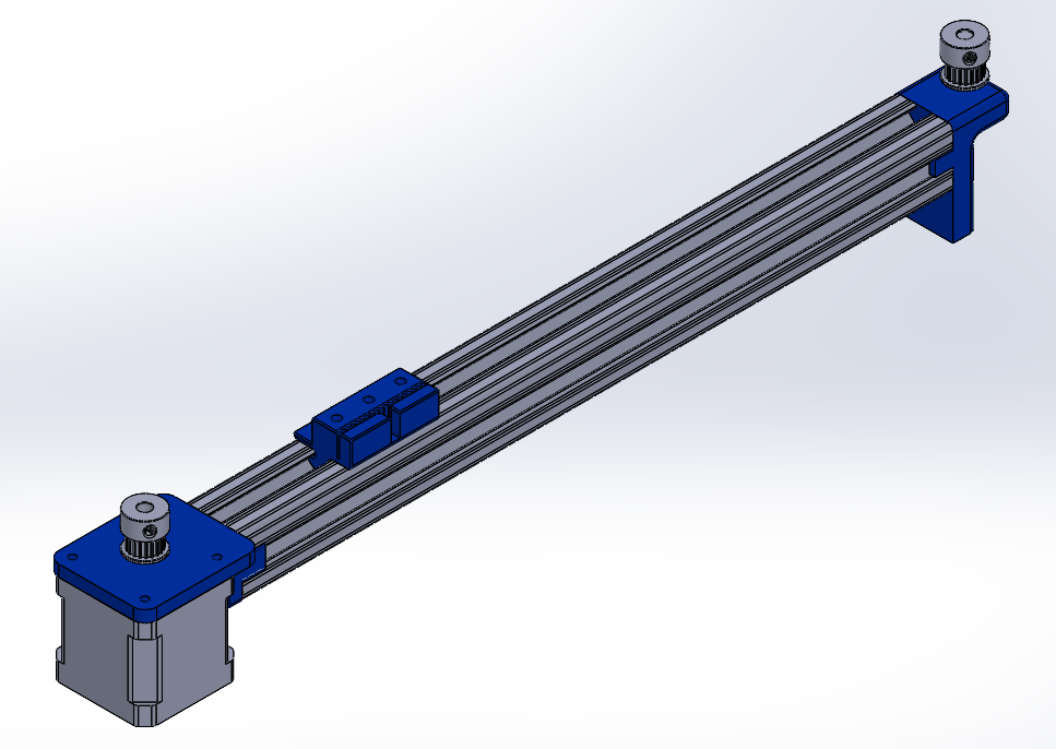
- Develop CAD model of the first linear stage (x axis).
- Manufacture the first linear stage. Once design is approved, manufacture the other pair.
- Design and manufacture the third linear stage (y axis) and manufacture it.
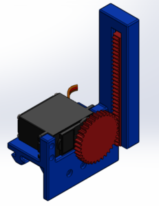
- Design and manufacture the z-axis actuator using a servo and rack-and-pinion system.
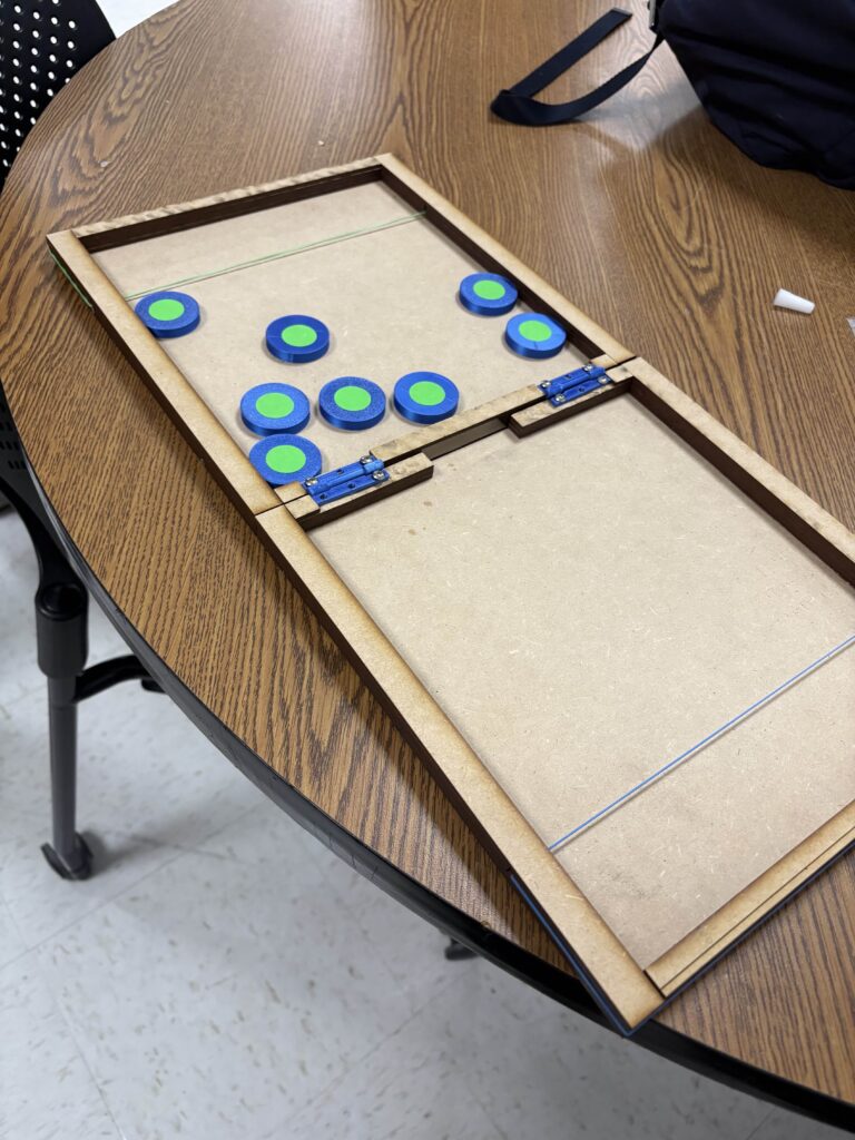
- Design and manufacture the board and assemble.
- Make any repairs and re-design parts if necessary.
- The MATLAB code is written.
- First, the code was developed to calibrate the machine by measuring the minimum and maximum travel limits, ensuring that the system does not collide with its mounts.
- Second, the code enables the Z-axis actuator tip to detect the puck and track its position.
- Finally, the code controls the actuator to push and hold the puck, transport it to the shooting position, and execute the shooting action.
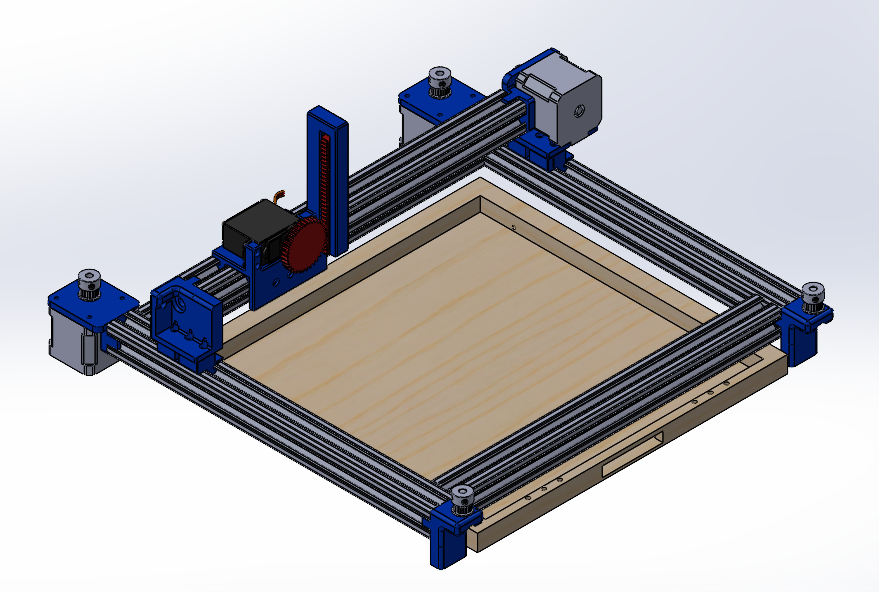
CAD model
- CAD Model of the entire assembly
2. CAD Model of first stage
3. CAD Model of Z axis actuator
Software
The following MATLAB code was written to control the system.
- cameraParams
- This code contains the parameters that define the lens on the camera and are used to estimate the distance for the dots. To make the detection easier, our puck has a green dot on top.
- TargetGreenDot
- This code detects the dots and manages all motion. The motion flow is described below.
- 1. When the camera detects any green dots, the machine moves the z-axis actuator so that it is positioned directly above the detected green dot.
- (1 alternative) When the camera does not detect any green dots, the machine moves the camera until a green dot is detected.
- 2. The z-axis actuator is lowered to the ground to grasp and hold the puck.
- 3. The puck is moved to the shooting position, pulling the rubber band and aligning the puck laterally at the center.
- 4. The z-axis actuator is raised to release the puck.
- 5. Go back to Step 1.
- This code detects the dots and manages all motion. The motion flow is described below.
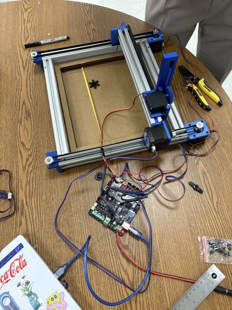
Pictures and Videos
Video of the final working prototype
Pictures of prototype during development