2025.5- Present Mechanical Team Lead
2025.5- Present Mechanical Team Lead
- Directed structural design, CAD development, and manufacturing for three prototypes in preparation for the April 2026 Design/Build/Fly competition.
- Planned and delivered a summer-long CAD training program for component leads, accelerating the team’s design cycle.
- Currently building Prototype 1 while planning development of Prototype 2.
2024.5 – 2025.5 Manufacturing team lead
- Responsible for manufacturing of the plane, including manufacturability assessment during planning and full construction.
- Successfully completed flight testing at an RC airfield in Massachusetts during Summer 2025.
2023.9 – 2024.5 CAD team General Member
- Built internal structure of the main wing, including spars, ribs and torsion boxes.
AIAA Design/Build/Fly: Facts
Mechanical Team (2025-26 Season)
- Merged CAD/Structures and Manufacturing teams to improve efficiency and accelerate development.
- Managing 15-member team building three prototypes (manufacturing proof, performance prototype, and competition aircraft) before competition.
- Implemented hot-wire foam cutting as the primary construction method to significantly reduce build time and cost.
Mechanical Team (2024-25 Season)
- Began with a three-member team and conducted composite layups of 2-oz fiberglass using female molds, while building wood wings and the empennage structure.
- Although development delays limited us to a single prototype that was not completed in time for the 2025 DBF competition, the aircraft successfully achieved flight shortly thereafter.
2024-25 Season Plane Technical Information
** Click here to jump to section of 2025-26 Plane Prototype 1 Technical Information.
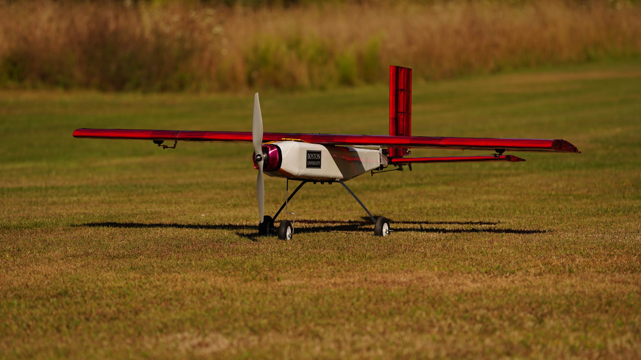
Airplane Specification:
- Wing span: 6 ft
- Tip-to-Tail length: 5 ft
- Main wing airfoil: Clark Y
- Payload Capacity: 30lb
- Max takeoff weight: 40lb
Video of flight demonstration
Technique Study
Various manufacturing techniques were studies to find the most suitable one for our prototype.
Manufacturing Method chosen:
- Fuselage: Female composite layup
- Material: 2oz Fiberglass
- Reason: Simple geometry makes composite layup efficient and easier. This method provides very high strength-to-weight ratio.
- Main wing / Empennage: Wood ribs, spars and leading edge
- Material: Balsa, Plywood
- Reason: Enables precise and detailed fabrication through laser-cutting, while offering good strength-to-weight ratio.
- Aircraft Skin: Film lamination
- Material: Ultrakote (heat-shrink plastic film)
- Reason: Adds structural rigidity through a tensioned skin while providing a smooth, aerodynamic surface finish.
- Female Mold: 3D printing
- Material: PLA
- Reason: Enables rapid and low-cost prototyping without requiring CNC milling (Wood was not allowed due to chips generation).
Manufacturing
Once the CAD design was finalized, we moved into manufacturing. Our primary methods were composite layup and wood work.
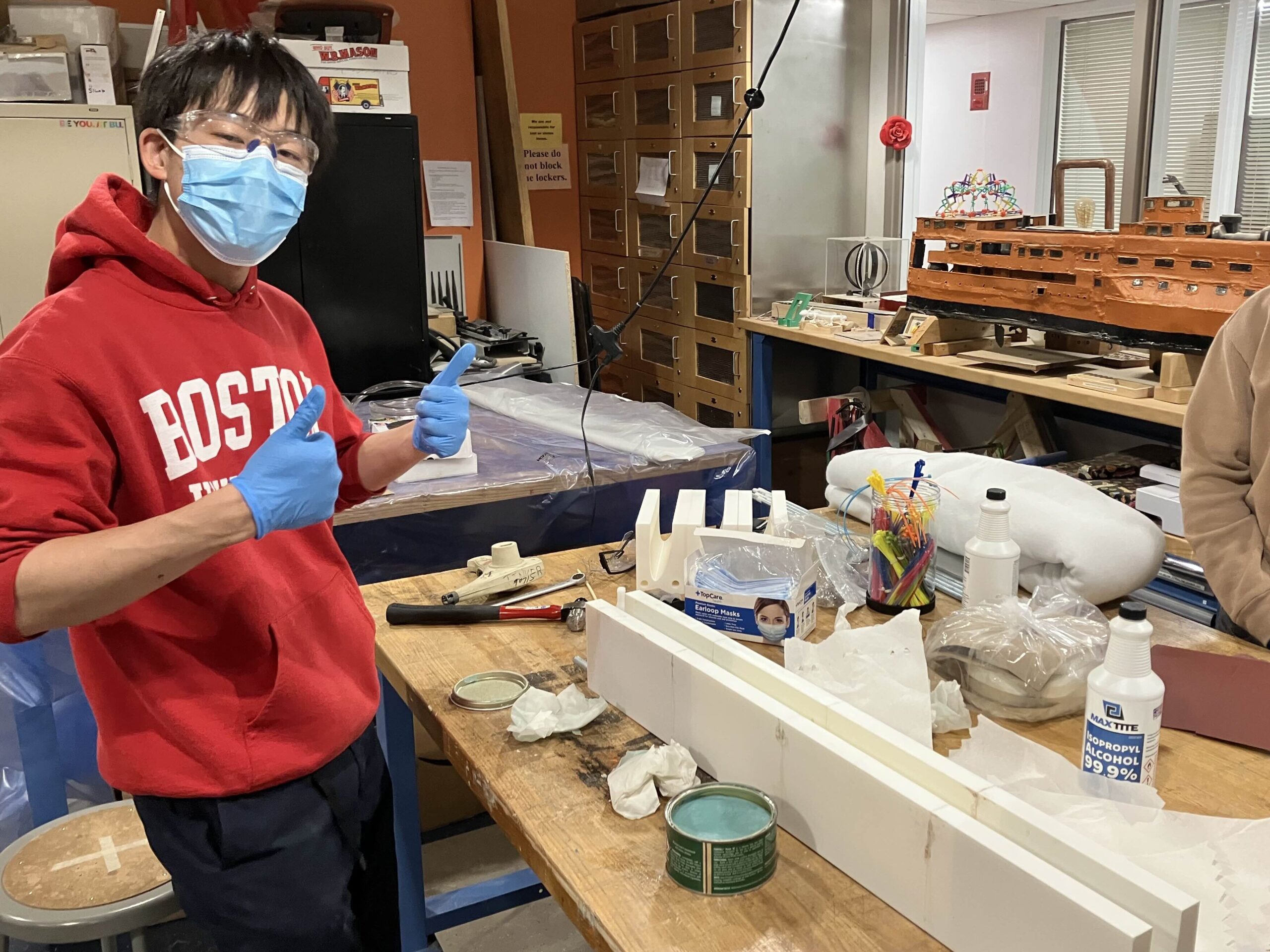
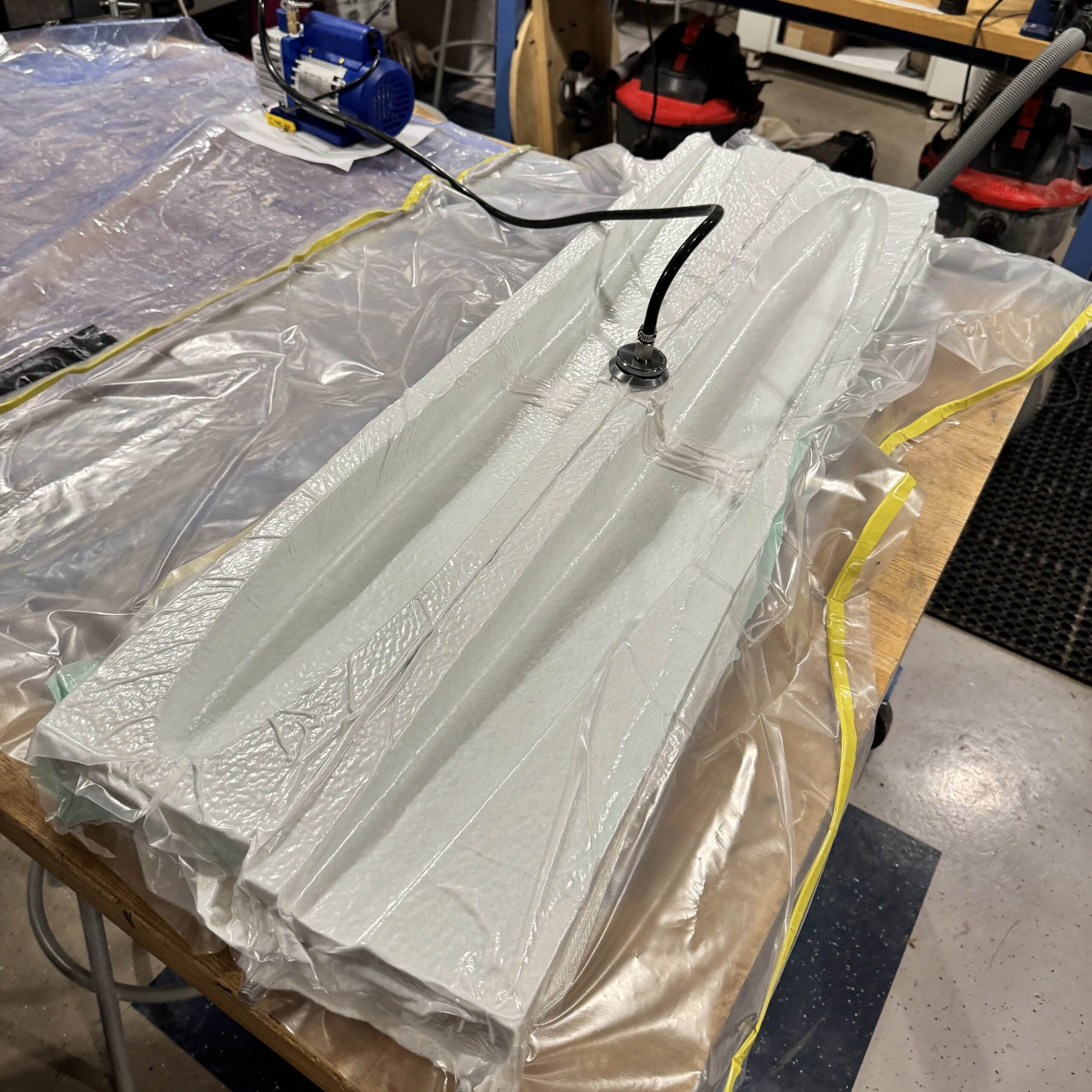
Composite Layup
- 2oz Fiberglass x 4 layers
- Used PLA female mold
- Vacuum bagged for 24 hours for curing
- Required about 10 hours of training before successful layup.
Picture of me doing layup
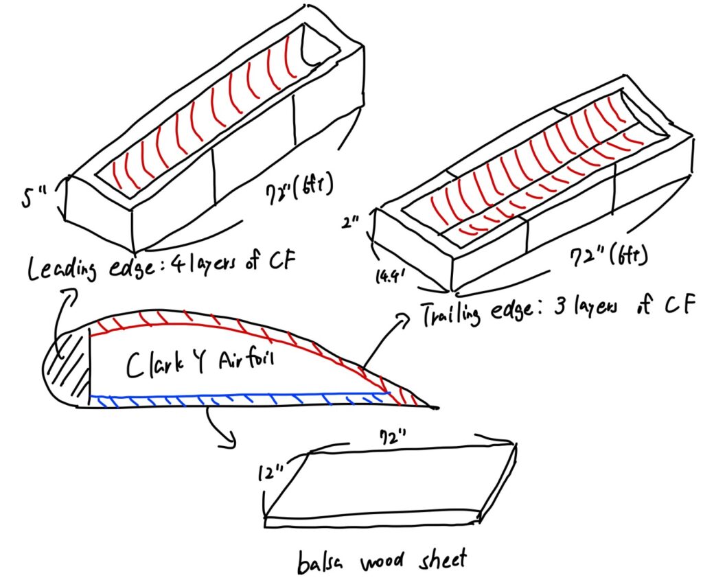
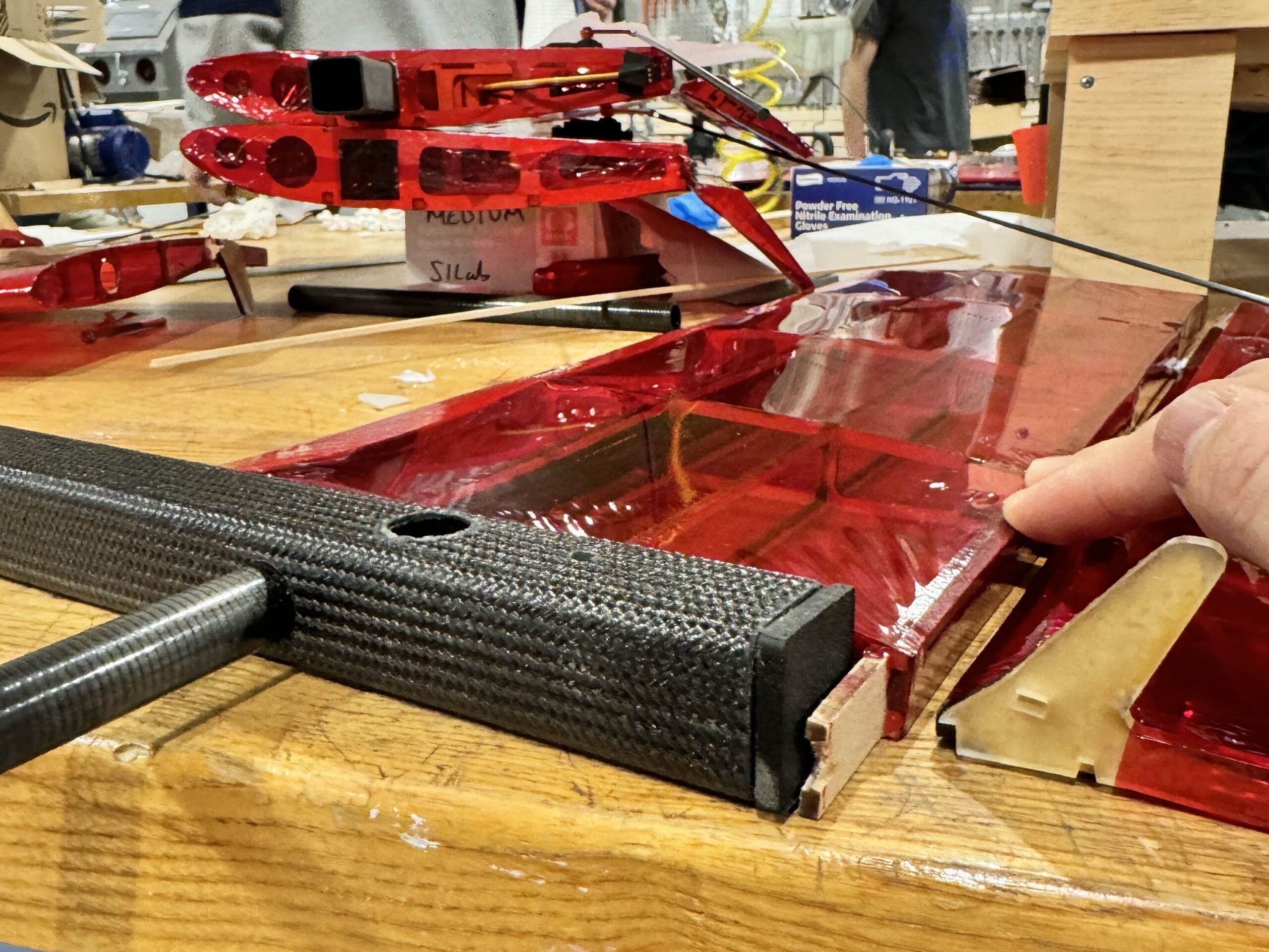
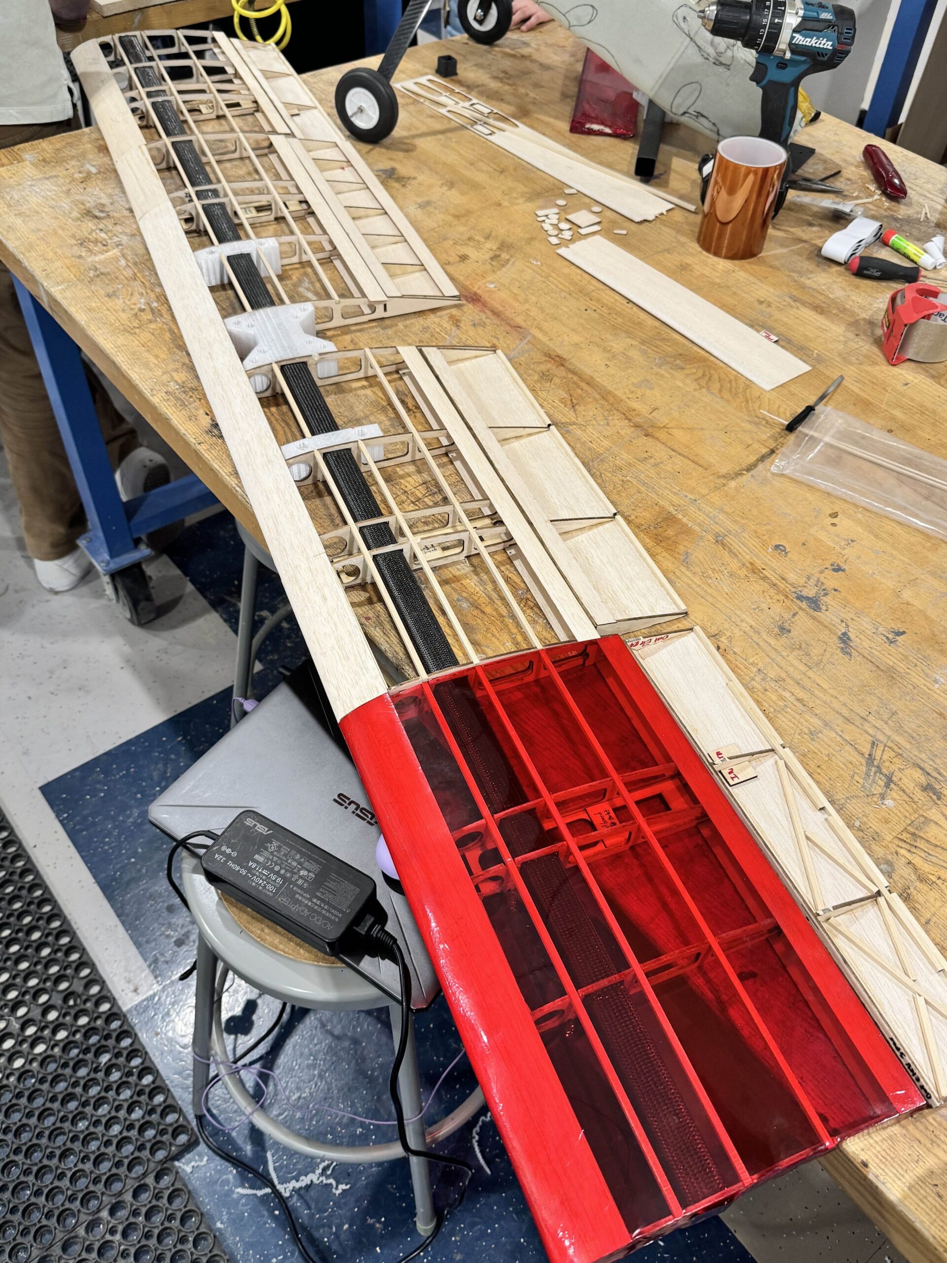
Wood construction + Lamination
- Used laser-cut balsa of varying thickness and CFRP spar.
- 1/8″: Ribs and stringers
- 1/16″: Spar plates
- 1/32″: Leading edge
- Used butt hinges for ailerons, which are inserted into slots.
- Laminated with plastic film.
2025-26 Season Prototype 1 Technical Information
State: Currently constructing
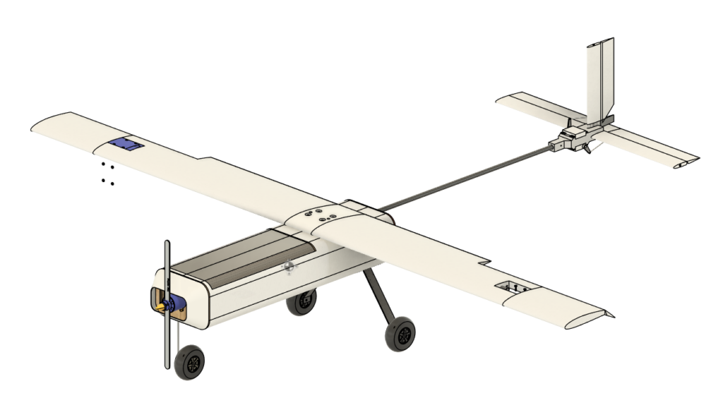
Airplane Specification:
- Wing span: 5 ft
- Tip-to-Tail length: 4 ft
- Main wing airfoil: NACA 2412
- Payload Capacity: 10lb
- Max takeoff weight: 20lb
Manufacturing Technique: Hot wire cutting
Design Iteration
We iterated quickly by holding frequent technical discussions and defining all critical dimensions before moving to CAD to detect design errors.
Design Flow
- Technical Discussion Workshop (3 hours)
- Established detailed structural concepts and selected materials.
- Defined all key dimensions including outer geometry and critical wall thicknesses.
- Comprehensive Design Review (~ 2 days)
- Prepared one-page summaries for each component, including key dimensions and hand sketches.
- Identified and resolved potential design conflicts across subsystems.
- CAD Development (~2 weeks)
- Developed the first full CAD iteration.
- Defined all mounting points at the start to ensure proper alignment and avoid integration errors.
- Critical Design Review + Improvement (1 week)
- Presented complete CAD model to cross-functional team leads for feedback.
- Implemented improvements and finalized CAD design.
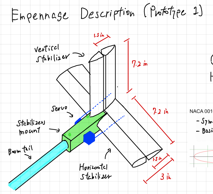
One-page summary of empennage created by me
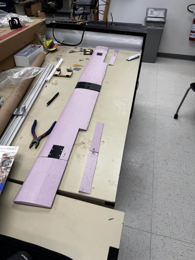
Manufacturing
Prototype 1 was made mainly using hot wire cut XPS foam.
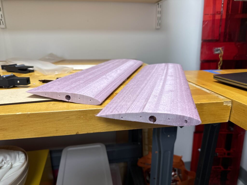
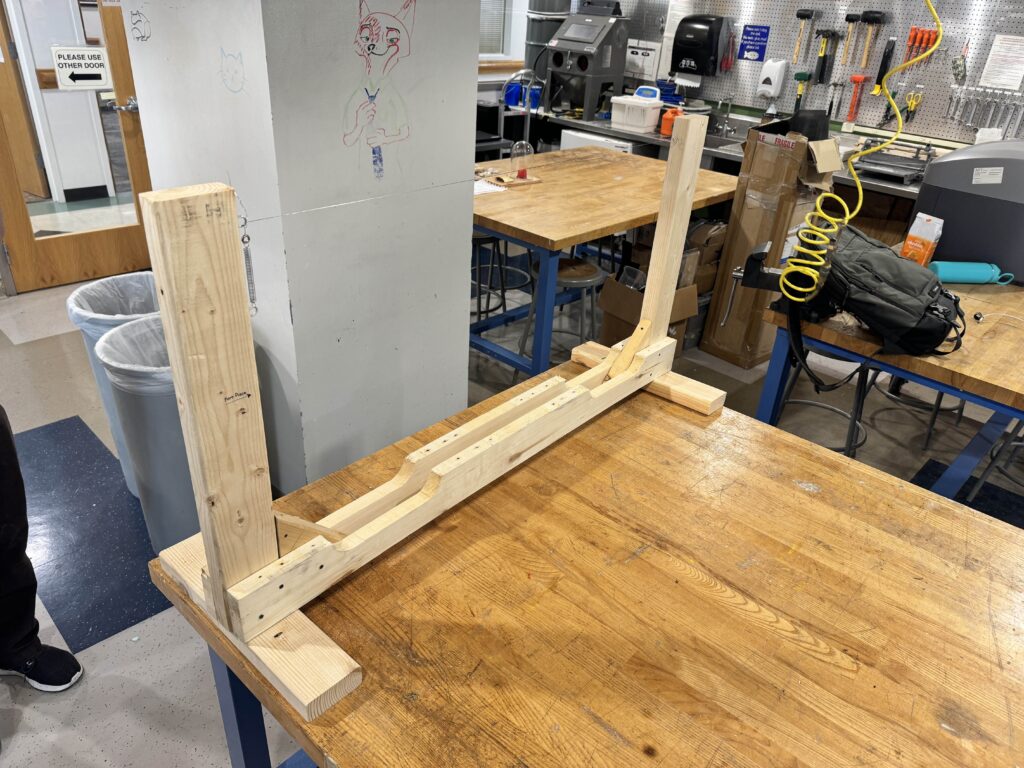
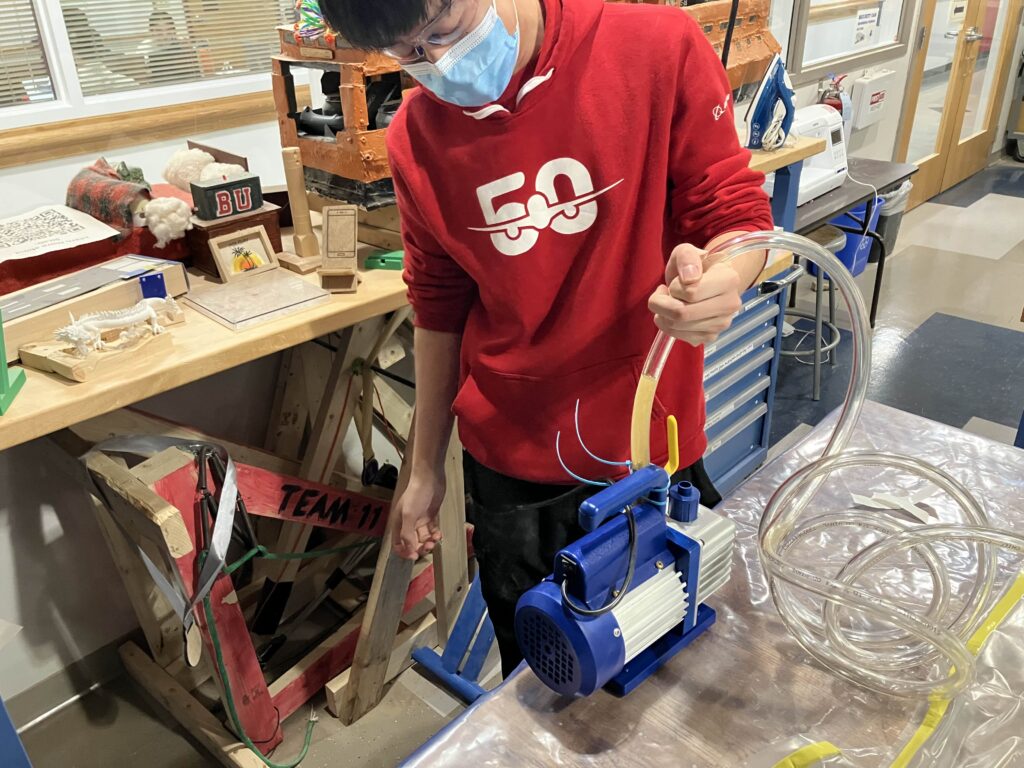
Hot wire cutting
- Used XPS foam with DIY hot wire cutter.
- Required about 4 hours of practice until successful fabrication.
- Hot wire cutter was also built using Nichrome wire and wood.
Picture of hot wire cutter